The Genius Hub system can control a wide variety of wet underfloor heating, in terms of the configuration of the underfloor heating, the floor covering and the hardware that is already part of the underfloor heating system. It can also control electric underfloor heating with the Powered Room Thermostat.
General Information
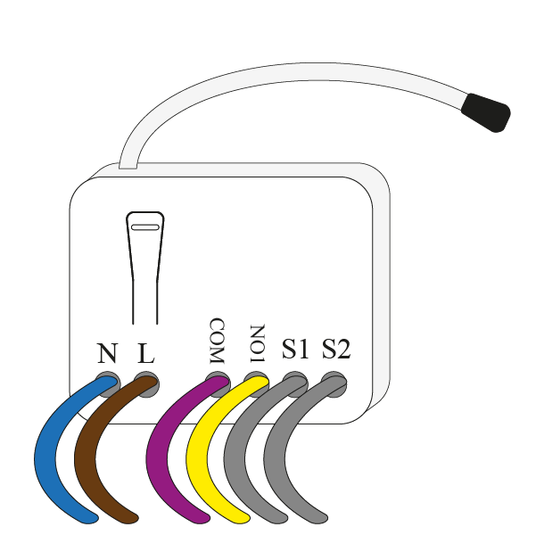
Standard wiring diagrams are provided with the system. To download a copy of the wiring diagrams, visit: https://www.geniushub.co.uk/wiring
All devices which control the heating in individual rooms and are purchased as part of a system direct from Genius Hub, such as Underfloor Receiver Units, Genius Radiator Valves or Room Sensors, are labelled with the room they control and are pre-linked to zones on the app.
The Single Channel Receiver is rated to 3A maximum. It can only be used to switch a zone valve, underfloor heating wiring centre or actuator and not a circulation pump. Wiring to a circulation pump directly will result in damaging the receiver units, voiding the warranty! The Electric Relay is rated to 11A maximum. The Electric Switch is rated to 13A maximum. The Powered Room Thermostat is rated to 16A maximum.
- There is no requirement for a programmer to be connected to the underfloor heating wiring centre. All of the control should be done from the Genius Hub receiver units. See wiring diagrams provided by the underfloor heating manufacturer to confirm the wiring in this installation manual.
- Using the appropriate wiring, as in accordance with BS7671 (or newer if such exists).
Do not attempt to wire in any devices if you are not 100% sure that you know what you are doing. Danger of electric shock! All wiring should conform to IEE regulations. The boiler and underfloor heating for the new devices must be electrically isolated before you commence work on any wiring!
Underfloor Wiring Centre
Depending on the control devices purchased, the Genius Hub system can be wired in a variety of ways, and to different voltage actuators and wiring centres. If you are using our Underfloor Wiring Centre, the terminals on the right-hand-side for the Manifold Pump and Underfloor Zone Valve are volt-free. See our wiring diagrams (link above) for how to connect to a 230v Pump/Zone Valve.
ERROR
The requested URL could not be retrieved
The following error was encountered while trying to retrieve the URL: https://confluence.geniushub.co.uk/*
Connection to 94.173.17.80 failed.
The system returned: (110) Connection timed out
The remote host or network may be down. Please try the request again.
Your cache administrator is webmaster.
Generated Wed, 27 Nov 2024 08:02:15 GMT by ip-10-19-3-49 (squid)
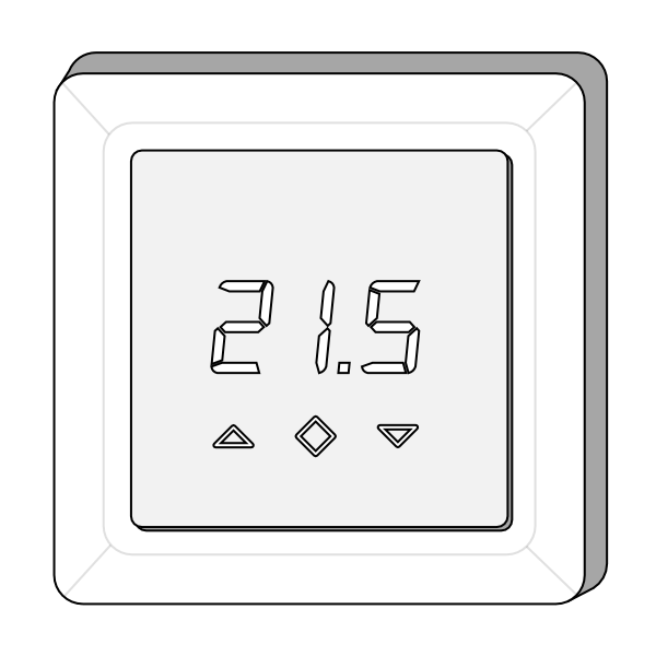
Powered Room Thermostat (Switched Live connections, or Single Zone / Underfloor Pump, Electric Underfloor)
If you are controlling an underfloor heating wiring centre or actuators which are 230v the Powered Room Thermostat will be used per zone controlled. If there are any existing controls, such as a thermostat, the wiring to these will need to be removed. The Powered Room Thermostat is wired into the room being controlled so it can detect the temperature, not near the actuators / wiring centre.
If you are only controlling a single zone of underfloor heating, you are likely to need to switch the underfloor circulation pump directly from the Powered Room Thermostat along with any zone valves or actuators. The Electric Switch can also be used in these situations.
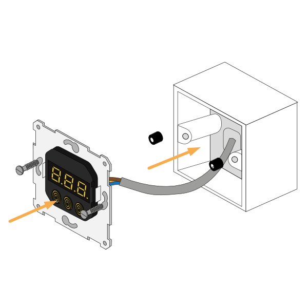
- The Powered Room Thermostat fits into a standard 1-gang pattress, we recommend approximately 40mm deep.
- If you are using a flush mount pattress it should screw in without any problems.
- If you are using a surface mount pattress, you may need to use the 2 spacers to bring the Powered Room Thermostat closer to the edge of the pattress.
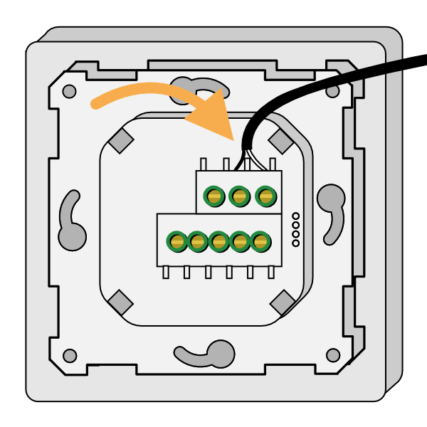
- Wire in the Temperature Probe or link provided into the 'Floor Sensor' terminals. (If using an existing probe, it must be 10kΩ at 25°C)
- Install the pattress into the room the Powered Room Thermostat is going to control.
- If using the floor probe, consider how this is going to get out of the pattress and it will be installed into the floor layer/onto the pipework of the wet underfloor.
- Wire in the mains power and the heating load to the Powered Room Thermostat.
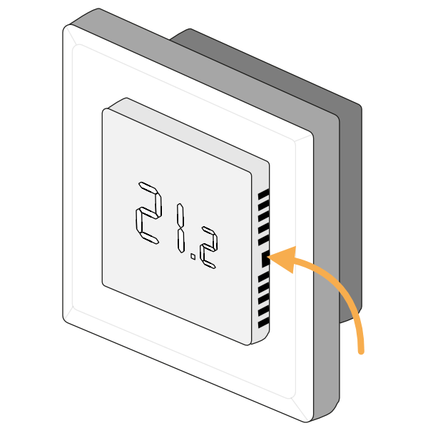
- To screw the Powered Room Thermostat to the pattress, first remove the screen by pushing a small flat-bladed screwdriver into the flat gap on each side of the screen. This will release the 2 spring clamps, and the screen and frame will become loose.
- Screw the Powered Room Thermostat to the pattress. Due to the cutouts to the side of the screen of the PRT, it can either be screwed directly to the pattress, or the screws can be mostly screwed in first and the Powered Room Thermostat placed over the screwheads and rotated.
- See 1.b if using a surface mount pattress, taking care to place the spacers between the device and the pattress.
- See 1.b if using a surface mount pattress, taking care to place the spacers between the device and the pattress.
- Place the frame on the Powered Room Thermostat and push the screen in place to secure the two parts to the main unit, ensuring the logo is at the bottom-left of the screen.
- If using the Floor Probe, fit this into the floor layer before powering on the Powered Room Thermostat.
In normal operation there will be no lights when the unit is off and one red light to the bottom-right of the display when heating.
Electric Switch (Switched Live connections, or Single Zone / Underfloor Pump)
If you are controlling an underfloor heating wiring centre or actuators which are 230v the Electric Switch will be used per zone controlled. If there are any existing controls, such as a thermostat, the wiring to these will need to be removed. The Electric Switch is often wired near the actuators / wiring centre and the Room Sensor or Room Thermostat placed in the room with the underfloor heating.
If you are only controlling a single zone of underfloor heating, you are likely to need to switch the underfloor circulation pump directly from the controller along with any zone valves or actuators. The Powered Room Thermostat be used in these situations.
- Always ensure that the boiler, underfloor heating and wiring for the Electric Switch is electrically isolated before you commence work on any wiring.
- Break out the relevant section of a 1-gang pattress for the wiring and fix the pattress to the wall. It is recommended that a 40mm pattress is used.
- Pull through the relevant wiring, allowing plenty of spare.
- Remove the front cover of the Electric Switch by placing a screwdriver in the slot under the device and levering the cover forwards.
- Wire in the Electric Switch as per the wiring diagrams provided, checking this is suitable as per the relevant installation manuals.
- Fit the Electric Switch into the pattress, ensuring there are no trapped wires. Screw in using standard pattress screws (provided), and check the unit is securely and safely attached to the wall.
- Reattach the front cover, starting at the top.
In normal operation there will be no lights when the unit is not heating and one or more red lights near the button when heating.
Electric Relay (Low Voltage/Volt free connections or Switched Live connections)
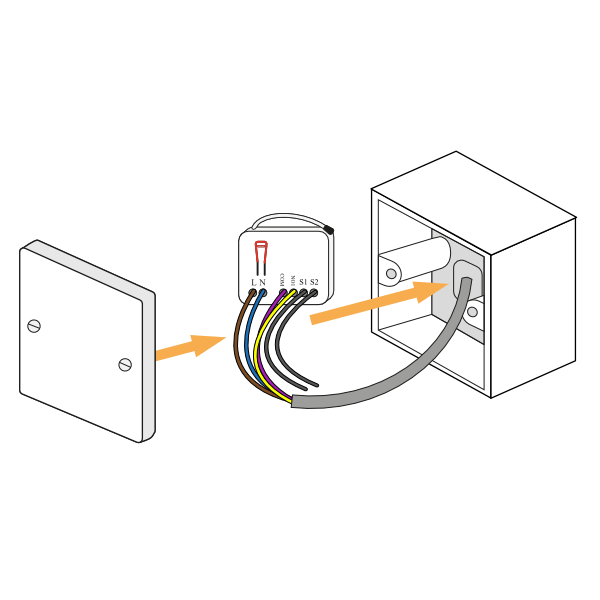
The Electric Relay can control an underfloor heating wiring centre or actuators which are 12v/24v/230v and will be used per zone controlled. If there are any existing controls, such as a thermostat, the wiring to these will need to be removed. The Electric Relay is often wired near the actuators / wiring centre and the Room Sensor or Room Thermostat placed in the room with the underfloor heating.
- Always ensure that the boiler, underfloor heating and wiring for the Electric Relay is electrically isolated before you commence work on any wiring.
- Break out the relevant section of a 1-gang pattress for the wiring and fix the pattress to the wall. It is recommended that a 40mm pattress is used.
- Pull through the relevant wiring, allowing plenty of spare.
- Wire in the Electric Relay as per the wiring diagrams provided, checking this is suitable as per the relevant installation manuals.
- Fit the Electric Relay into the pattress, ensuring there are no trapped wires, fit the blanking plate to the front of the pattress. Screw in using standard pattress screws, and check the unit is securely and safely attached to the wall.
